
Forward Kinematics of Movemaster RM-501 
Introduction
Mitsubishi Movemaster RM-501 is a entry level industrial robot with five rotational joints having five degree of freedoms. Forward kinematics refers to the use of the kinematic equations of a robot to compute the position of the end-effector from specified values for the joint parameters. The kinematics equations of the robot are used in robotics, computer games, and animation. The reverse process that computes the joint parameters that achieve a specified position of the end-effector is known as inverse kinematics.
The essential concept of forward kinematic animation is that the positions of particular parts of the model at a specified time are calculated from the position and orientation of the object, together with any information on the joints of an articulated model. So for example if the object to be animated is an arm with the shoulder remaining at a fixed location, the location of the tip of the thumb would be calculated from the angles of the shoulder, elbow, wrist, thumb and knuckle joints. Three of these joints (the shoulder, wrist and the base of the thumb) have more than one degree of freedom, all of which must be taken into account. If the model were an entire human figure, then the location of the shoulder would also have to be calculated from other properties of the model.
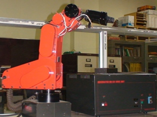
Figure 1: Movemaster RM-501
Theory
MOVEMASTER RM-501
The Mitsubishi Movemaster RM-501 robot is a robotic arm having five degrees of freedom with five rotational joints. The robot unit consists of the waist, shoulder, elbow, wrist pitch, and wrist roll. These are actuated with DC motors to each of which two encoders are associated which allow differential directional information to be read for each joint.
Overall size:
The Robot Unit, including the base, weighs approximately 27 kg. The overall size of the robot is comparably small with a circular work envelope of 445mm maximum horizontal reach and a maximum payload of 1.2kg.
Components:
In addition to the robot itself, the complete robotic system for the Mitsubishi Movemaster consists of several components, which are shown in the following Figure 2:

Figure 2: Movemaster RM 501 components
The main components of the RM-501 include the Robot and the Drive Units. Options include the Teaching Box and the standard hand. The RM-501 drive unit provides the intelligence and control for the robot unit. The Drive Unit computes all arm control information for each instruction. It handles arm velocity, acceleration, deceleration and movement trajectories for the user. The Teaching Box allows a user to manually move all joints of the Robot Unit and store positions as desired. The Drive Unit is interfaced to the Computer host processor via a controller interface.
Range of movement of each joint:
| Waist Joint: | $$ 300 $$ |
|---|---|
| Shoulder Joint : | $$ 130 $$ |
| Elbow Joint: | $$ 90 $$ |
| Wrist Bend: | $$ \pm 90 $$ |
| Wrist Roll: | $$ \pm 180 $$ |
Robot Kinematics:
Robot kinematics involves computing the end effector's position from the joint angles and vice versa for controlling the position of robot. The Mitsubishi RM-501 robot has 5 degrees of freedom (Figure 2) and the ability to grip with its two fingers. Its position can be described by the vector of joint coordinates \( q = [q_1\quad q_2\quad q_3\quad q_4\quad q_5]^T \) and the vector of external coordinates \( r = [ x\quad y\quad z\quad \phi \quad \psi ]^T \) . Figure 3 shows the robots arm with its basic dimensions, from which the kinematics can be derived, i.e. the link between the \( q \) and \( r \) vectors.

Figure 3: Degrees of freedom of the RM-501 robot
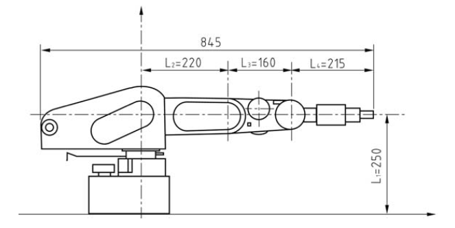
Figure 4: Dimensions of the RM-501 robot
Forward Kinematics
Forward kinematics involves computing the position and orientation of the end effector when the relative movements at various connections and other relevant geometrical parameters are prescribed. The forward kinematics of a kinematic chain can be established by defining a coordinate system at the root of each link and then defining transformation matrices between subsequent coordinate systems as:
$$ A^0_1, A^1_2, A^1_2, ...... A^{n-1}_n $$
For rotational joints, each matrix will then contain the joint angle \( \hat{I} \)¸ \( n \) as a variable. The overall transformation from the earth fixed reference frame to the end effector fixed reference frame is then given by
$$ A^0_n = A^0_1 A^1_2 A^1_2 ...... A^{n-1}_n $$
For each joint of the robot : \( A^{i-1}_i \) the Denavit-Hartenberg matrix contains four parameters that fully define coordinate transformation from the coordinate system attached to the previous link to the coordinate system attached to the next link. The four parameters and a description of their meaning is given in Table
| Parameter | Description |
|---|---|
| $$ a_i $$ | The distance between \( Z_{i-1} \) to \( Z_i \) measured along \( X_i \) |
| $$ \alpha_i $$ | The angle between \( Z_{i-1} \) and \( Z_i \) measured along \( X_i \) |
| $$ d_i $$ | The distance between \( X_{i-1} \) to \( X_i \) measured along \( Z_i \) |
| $$ \theta_i $$ | The angle between \( X_{i-1} \) and \( X_i \) measured along \( Z_i \) |
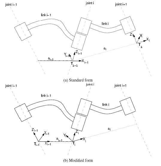
Figure 5: The modified Denavit-Hartenberg notation.
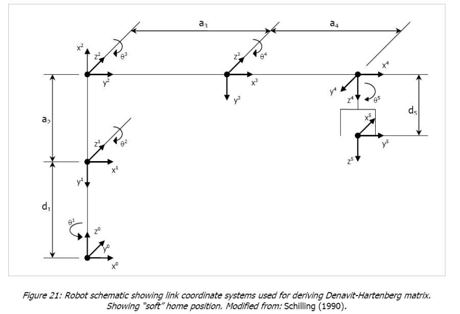
The Denavit-Hartenberg parameters derived for the Mitsubishi Movemaster RM-501 is given in table below. The schematic of the robot with the intermediate coordinate systems used to derive the matrix is given in Figure.
| $$ i $$ | $$ a_i $$ | $$ \alpha_i $$ | $$ d_i $$ | $$ \theta_i $$ | Home |
|---|---|---|---|---|---|
| $$ 1 $$ | $$ 0 $$ | $$ -90^o $$ | $$ 250 $$ | $$ \theta_{waist} $$ | $$ 0^o $$ |
| $$ 2 $$ | $$ 220 $$ | $$ 0^o $$ | $$ 0 $$ | $$ \theta_{shoulder} $$ | $$ -90^o $$ |
| $$ 3 $$ | $$ 160 $$ | $$ 0^o $$ | $$ 0 $$ | $$ \theta_{elbow} $$ | $$ 90^o $$ |
| $$ 4 $$ | $$ 0 $$ | $$ -90^o $$ | $$ 0 $$ | $$ \theta_{wristpitch} $$ | $$ 0^o $$ |
| $$ 5 $$ | $$ 0 $$ | $$ 0^o $$ | $$ 215 $$ | $$ \theta_{wristroll} $$ | $$ -90^o $$ |
From Schilling (1990) the arm matrix can be derived by analogy to general arm matrix for five axes articulated robots.
This matrix can be understood as being composed of a vector P defining the position the end effector in space, and a 3 by 3 matrix R defining the orientation of the end effector: